Light Module DIY
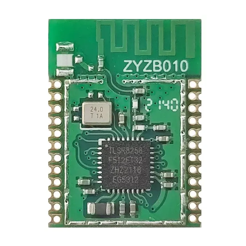
Model ZYZB010 manufactured by eWeLight
Zigbee ID: ZB-CL01 | ZB-SW02
Confirmed working with
If the device is following Zigbee standards it is possible it will work with other gateway solutions, it is just not confirmed as working yet!
ZigBee 3.0 1-5 channel switch,Plug,1-5 PWM Light(W,CW,RGB,RGBW,RGBCW) (multiple variants exist, all with model ZYZB010)
Telink TLSR8258 module
Connections
    _____________________
   |  ____    __    __   |
   | | |  |__|  |__|  |  |
   |            ZYZB010  |
 1 | Vcc             RST | 24
 2 | Gnd              C1 | 23
 3 | SWS-A7           C0 | 22
 4 | D2            B7-Rx | 21
 5 | D3            D7-Tx | 20
 6 | C3               B6 | 19
 7 | C2               B1 | 18
 8 | nc               B5 | 17
 9 | nc               B4 | 16
10 | D4               A1 | 15
11 | nc               C4 | 14
12 | A0               nc | 13
   |_____________________|
| Pin | 1-5 On/Off switch | 1-5 PWM outputs | 1-3 Bi-stable relay output (Low power module) | |
|---|---|---|---|---|
| 1 | VCC | Power Supply 3.3V | Power Supply 3.3V | Power Supply 3.3V |
| 2 | GND | GND | GND | GND |
| 3 | SWS-A7 | Debug and Download interface: SWS | Debug and Download interface: SWS | Debug and Download interface: SWS |
| 4 | D2 | GPIO : D2 | GPIO : D2 | IN 2 : Switch Signal Input, Active Low, Pair mode |
| 5 | D3 | GPIO : D3 | FAC_RST, Active Low, Pair mode | GPIO : D3 |
| 6 | C3 | OUT 5 : Relay signal output, Active High | PWM2 (Warm White) | IN 1 : Switch Signal Input, Active Low, Pair mode |
| 7 | C2 | IN 5 : Switch Signal Input, Active Low, Pair mode | PWM1 (Cold White) | OUT 1 ON : 15 ms High pulse |
| 8 | NC | Not Connected | Not Connected | Not Connected |
| 9 | NC | Not Connected | Not Connected | Not Connected |
| 10 | D4 | IN 4 : Switch Signal Input, Active Low, Pair mode | GPIO : D4 | OUT 2 OFF : 15 ms High pulse |
| 11 | NC | Not Connected | Not Connected | Not Connected |
| 12 | A0 | IN 1 : Switch Signal Input, Active Low, Pair mode | GPIO : A0 | OUT 2 On/Off Status, Active High |
| 13 | NC | Not Connected | Not Connected | Not Connected |
| 14 | C4 | OUT 4 : Relay signal output, Active High | PWM3: (Red) | OUT 3 OFF : 15 ms High pulse |
| 15 | A1 | Pair Mode LED, flash in Pair Mode, else Low | GPIO : A1 | Pair Mode LED, flash in Pair Mode, else Low |
| 16 | B4 | OUT 1 : Relay signal output, Active High | PWM4 (Greeen) | OUT 2 ON : 15 ms High pulse |
| 17 | B5 | OUT 3 : Relay signal output, Active High | PWM5 (Blue) | IN 3 : Switch Signal Input, Active Low, Pair mode |
| 18 | B1 | OUT 2 : Relay signal output, Active High | GPIO : B1 | OUT 1 On/Off Status, Active High |
| 19 | B6 | GPIO : B6 | GPIO : B6 | GPIO : B6 |
| 20 | D7 | GPIO : D7 | GPIO : D7 | OUT 1 OFF : 15 ms High pulse |
| 21 | B7 | GPIO : B7 | GPIO : B7 | OUT 3 On/Off Status, Active High |
| 22 | C0 | IN 3 : Switch Signal Input, Active Low, Pair mode | GPIO : C0 | OUT 3 ON : 15 ms High pulse |
| 23 | C1 | IN 2 : Switch Signal Input, Active Low, Pair mode | GPIO : C1 | GPIO : C1 |
| 24 | RST | nRST, Active Low | nRST, Active Low | nRST, Active Low |
Minimal use: connect Vcc and Gnd, and OUT and IN as needed.
Tips
- Switching output (1-5 Ch On/Off type) work only with pulse switches, no on/off switch input.
- When not paired to Zigbee network, module goes automatically into pairing mode.
- INputs have internal pull-up, so only need a switch to ground.
- To go into pairing mode, connect one of the switch inputs to Gnd for more than 5 seconds. The (relay) output will blink a couple of times, the pairing indicator output will keep blinking until paired.
- PCB antenna is not as powerful/sensitive as usual for complete devices. I needed to be close to my Zigbee hub to get pairing working the 1st time.